Platforms/Import into Software Platform/
Import Generated PLC in SIEMENS Simatic Manager
Introduction
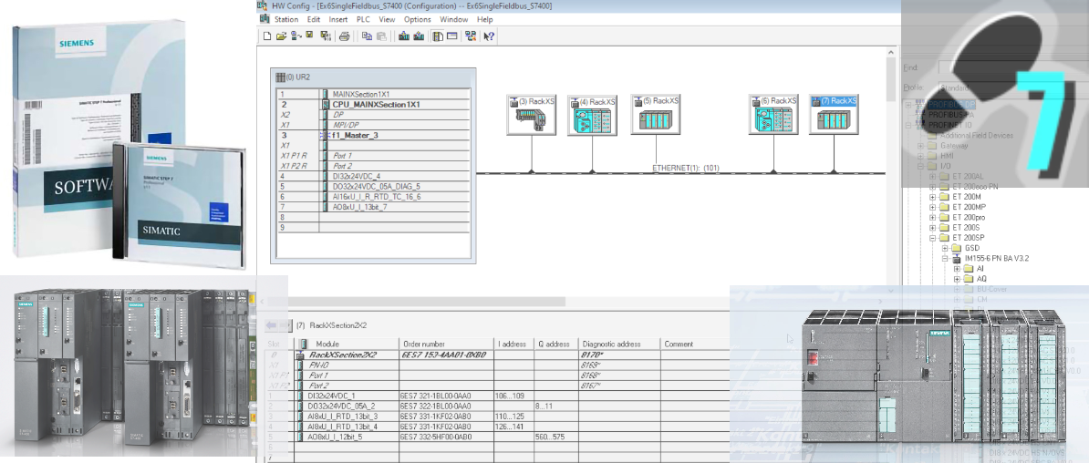
STEP 7is a well-known software package developed by Siemens primarily designed for programming Siemens S7-300/400 series of PLCs. These PLCs are widely used in industrial automation due to their reliability, flexibility, and scalability. Step7 provides a comprehensive environment for developing PLC programs, configuring hardware, and managing communication between PLCs and other devices.
Step7 has a user-friendly interface that enables efficient programming and debugging of PLC applications. It offers a range of tools for creating, editing, and organizing PLC programs, such as a graphical editor for designing ladder logic diagrams, a function block editor, and a structured text editor. The software also includes features like syntax highlighting, code completion, and debugging tools to assist in the development and troubleshooting process.
In the steps presented below we are providing a procedure on how to import a PLC created with PLCCreator in Step7 Simatic Manager.
1.
Download Project from PLCCreator
In some cases on mobile devices or smaller screens, if the button is not visible, you may first click the toolbar menu button to open the PLC details toolbar.
Unzip the file preferably in the separate folder.
2.
Create New Project and Open Hardware Configuration
Open Simatic Manager and create a new project. Add a new station with the same hardware platform as your CPU, optionally you can rename it. Click the station icon (1) and double-click "Hardware" (2) to open the hardware configuration tool "HW Config".

3.
Import Hardware Configuration - Open File Import Dialog
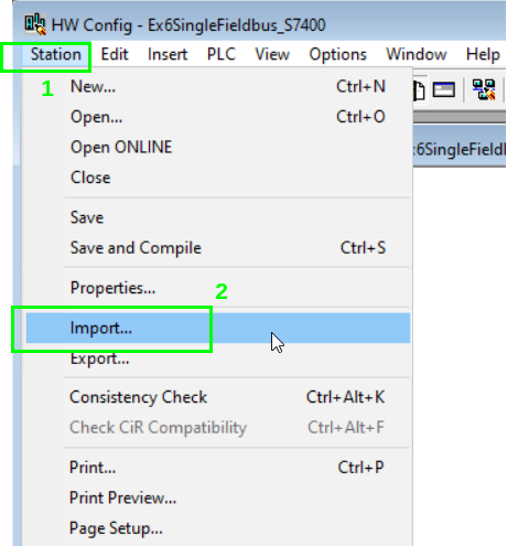
On the menu click "Station" (1) and then "Import" (2), to open the file import dialog:
4.
Import Hardware Configuration - Select .cfg File
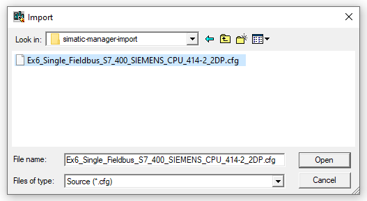
Point to the directory where you have unzipped the zip file and select the.cfgfile that contains your PLC name and click "Open" to start the import process:
During import process you may need to respond on additional dialogs and messages described in the substeps4a,4band4c.
4a.
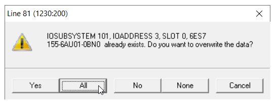
Interface Modules Overwrite Dialog
Click "All" on the overwrite dialog for interface modules of the remote racks:
4b.
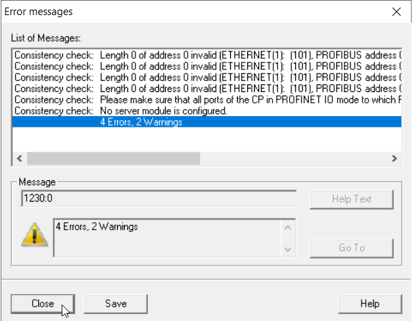
Errors Summary Window
Click "Close" if import errors summary window appears:
4c.
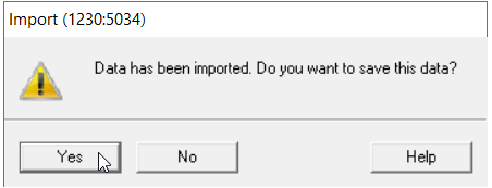
Save Imported Hardware Configuration Dialog
Click "Yes" on the save dialog for hardware configuration:
5.
Save/Compile Project
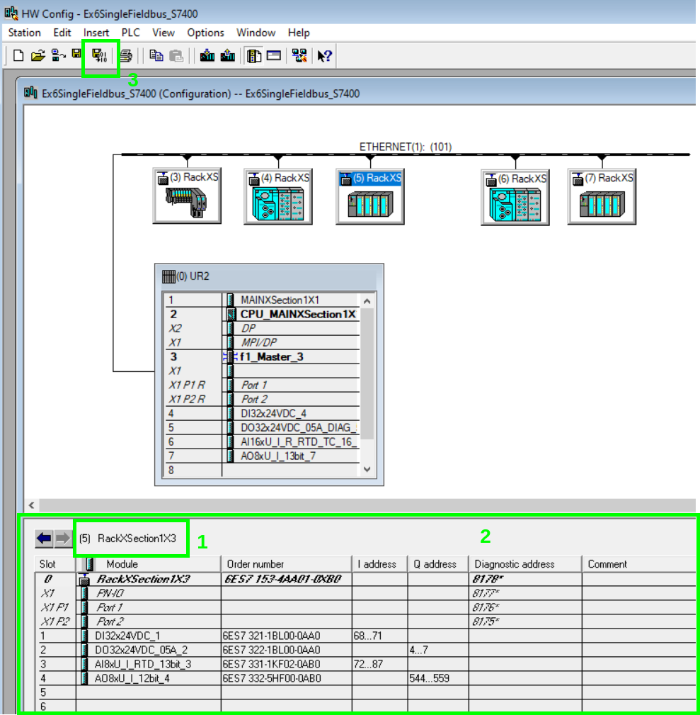
Upon completion you will see your devices in the hardware configuration workspace. You can drag the stations to rearrange them by group name as shown on Figure 7. You can find the rack name in the title (1) of the rack modules panel (2). Please note that underscore character "_" in rack names is replaced with alphanumeric character "X".
You can explore the rack modules by clicking on the rack icon and see the modules in the modules panel.
Click Save/Compile icon (3) and close the "HW Config" application if there are no errors.

If the imported project has ET200SP racks the compiler will throw an error that ET200SP server module (the rack termination module) is not installed. In this case you need to complete the additional actions described in the substeps5aand5b, otherwise go ahead to step6.
5a.
SIMATIC Manager Server Module Error
Initially the general compile error appears as shown in Figure 8:
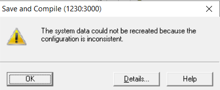
Click on "Details" to open the compilation error details window as shown on Figure 9:
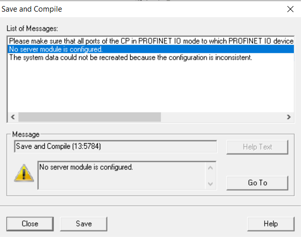
5b.
Add Server Module at the End of the ET200SP Rack
On the workspace click the "ET200SP" rack (1), its modules will appear on modules panel (2). Expand the fieldbus IO group of the same type as "ET200SP" rack fieldbus, in this instance "Profinet IO" (3), expand the "IO" group (4), expand the "ET 200SP" group (5), expand any of "IM 155-6 PN" groups (6), expand the "Server modules" group (7), click the "Server module V1.1" and drag it to the first free slot on modules panel, in this instance slot 5:
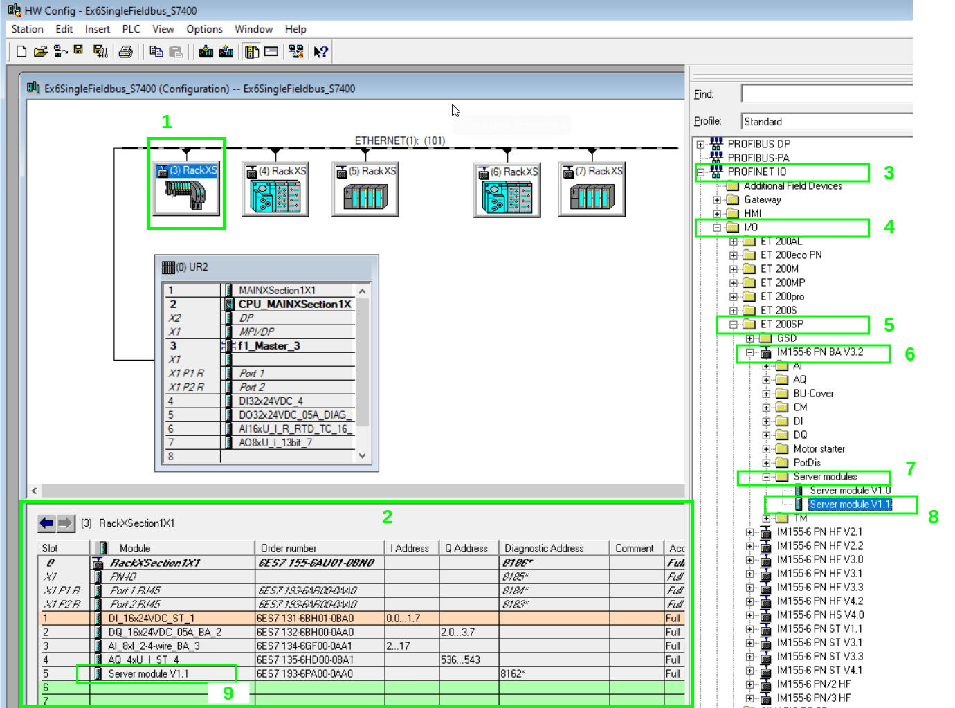

Repeat the compilation action from step5.
6.
Open Symbols Application
On main "Simatic Manager" window expand the project group (1), expand the station group (2), expand the Main Rack Group (3), click the "S7_Program" (1) folder and on the workspace double-click the "Symbols" icon (5):
Click "Yes" on the save dialog for hardware configuration:

7.
Import Symbols - Open File Import Dialog
On the menu click "Station" and then "Import", to open the file import dialog:

8.
Import Symbols - Select .seg File
Point to the directory where you have unzipped the zip file and select the.seqfile that contains your PLC name and click "Open" to start the import process:
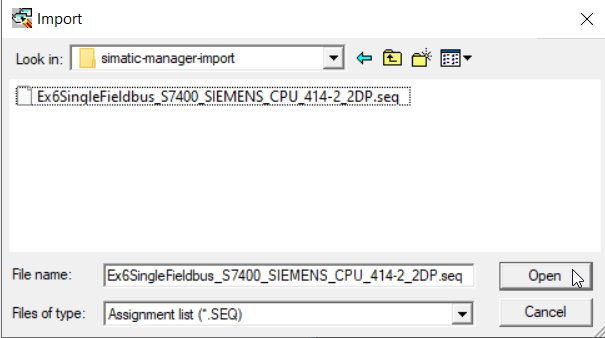
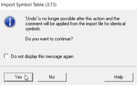
Before the start of the import process, the continue dialog appears as shown in Figure 14. Click "Yes" to continue:
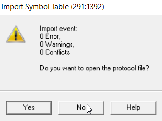
At the end of the import process, the protocol dialog appears as shown on Figure 15. You can answer "No":
9.
Import Symbols - Save Symbol Table
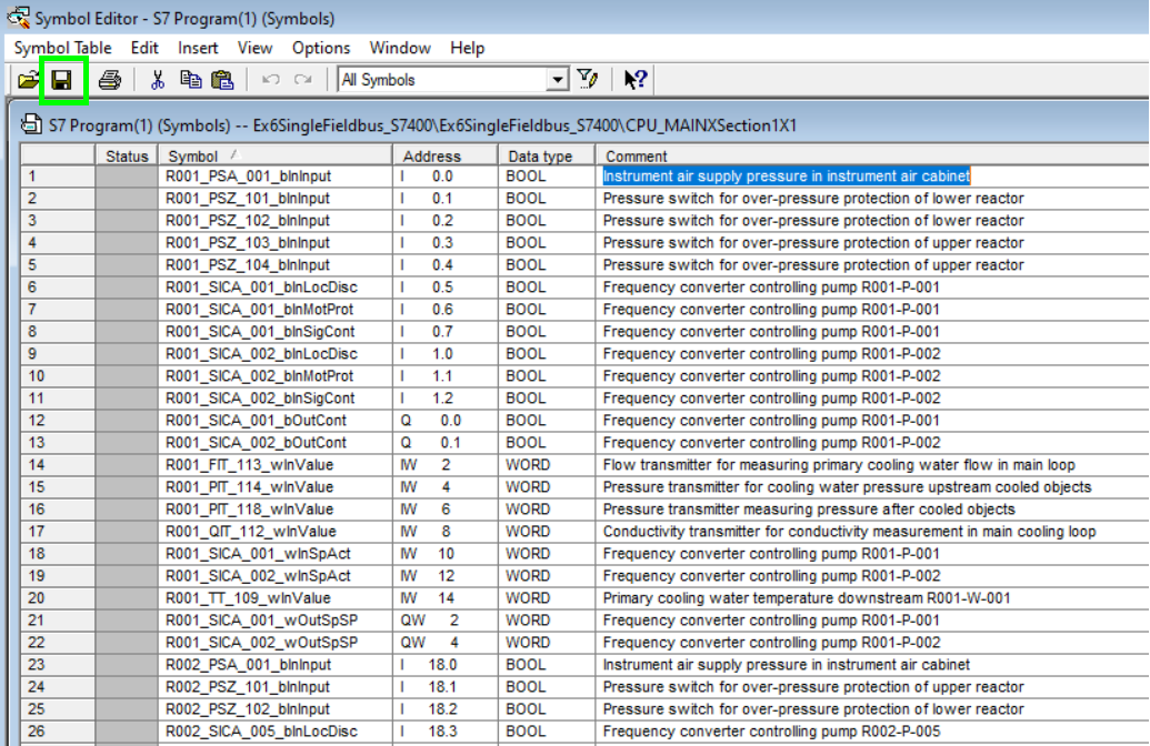
Upon completion the symbols appear in the symbols table. This table corresponds to theIO Listuploaded in the PLC generation process in PLCCreator, and you can explore it so see all tags. Click "Save" icon to save the table:
