


Create PLC with PLCCreator
Overview

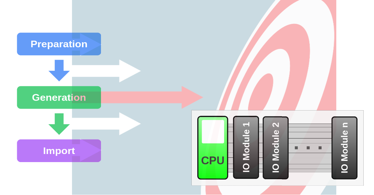
PLCCreator enables rapid PLC creation through 7 straightforward steps, structured into 3 clear phases:
Preparation
Youwill need to:
- Analyze your project documentation (requirements specifications, P&IDs, instrument lists)
- Determine the appropriate PLC architecture for your system
- Prepare an IO list in the required format for PLCCreator
This preparation ensures PLCCreator can effectively generate your PLC configuration.
Phase includes:
Generation
PLCCreator then guides you through the configuration process, offering the same streamlined workflow across all supported hardware and software platforms.
This phase produces ready-to-use files for your chosen PLC software platform .
Phase includes:
- Step 3: Select CPU Module
- Step 4: Select PLC Architecture (from Step 1)
- Step 5: Upload IO List (from Step 2)
- Step 6: Generate PLC
Import
The final step: simply import your generated files into your preferred PLC software platform .
Your complete PLC project will include hardware configuration, IO signal assignments, and ready-to-use PLC tags.
Phase includes:
Quick guide
Determine PLC Architecture
Select the appropriate PLC architecture for your project:
Create IO List
Convert your instrument IO list or index into the standardized andarchitecturespecific IO List format using Excel.
The templates are available on the IO List Templates page.
Select PLC Architecture
- Access the PLC Architecture page via the navigation panel
- Select your pre-determined architecture from Step 1
Upload IO List
- Select either:
- "Upload IO Signals" ( Upload IO Signals )
- or "Upload IO Devices" ( Upload IO Devices )
- Upload your prepared .csv file from Step 2
- Confirm by clicking "Save"
Generate PLC Configuration
- Access the Generate page via the navigation panel
- Configure/select:
- Main Rack Type: Standard Rack or Standalone CPU
- Main Rack Group
- Main Rack Fieldbus (for multiple fieldbus architectures)
- Optional contingency settings
- Save your configuration
- Initiate generation process by clicking the "Generate" button
Upon completion, you will be redirected to the PLC Details page.
Import to Engineering Software
- Select your software platform:
Refer to the following chapters for detailed implementation guidance.
Introduction
In this guide, we'll provide you with step-by-step instructions for generating a PLC configuration, demonstrated through a real-world project example.
Project Overview:
We will create a PLC configuration for a control system comprising three electrical cabinets (Figure 1):

The project documentation includes an instrument IO list, available for download: Customer-Instrument-IO-List.xlsx
Figure 2 shows a condensed view of this IO list:

System Requirements:
- Main Cabinet: Siemens ET200MP platform serving as the main rack with CPU module (specified model: CPU_1515-2_PN).
- Remote Cabinet: Compact Siemens ET200SP hardware platform.
- Machine 1: IP67-rated ET200Pro platform for direct machine mounting (cabinetless installation).
Step 1:
Determine PLC Architecture
PLCCreator enables you to build PLC systems using 3 distinct architectural models:
Selecting the optimal architecture is crucial for project success. For the system shown in Figure 1 , the Single Fieldbus Architecture architecture represents the most suitable solution.
While a Multiple Fieldbuses Architecture approach could be considered (given the two remote IO racks with potential for separate fieldbuses), we recommend Single Fieldbus Architecture for this implementation due to its superior simplicity.
Step 2:
Create IO List
IO lists serve as the critical data interface between your documentation and PLCCreator. They arearchitecture specific and each PLC architecture supports two standardized IO list formats:
For this project (based on the architecture selected in Step 1 and the signal-based source data), you'll need to use Signal IO List for Single Fieldbus Architecture with its template: Signal IO List Template Single Fieldbus Common.xlsx
IO List Transformation Process
Figure 3 illustrates the workflow for converting user-provided IO data into PLCCreator-compatible format:
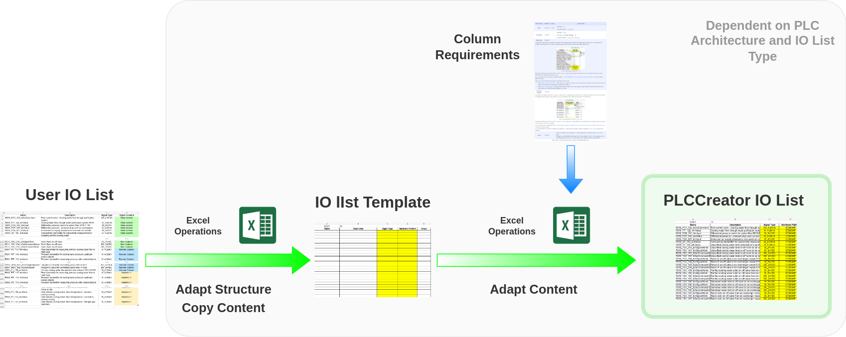
The transformation involves two key stages:
- Structural adaptation: Adapt the user IO list format with the PLCCreator template structure
- Content standardization: Modify data to meet architecture-specificcolumn requirements
Understanding the Template Structure
The Signal IO List template contains 5 columns organized into 2 functional groups:
IO Module Creation Columns:
- Name
- Description
- Signal Type
Inherited from Signal IO List for Single Rack Architecture
Rack Creation Columns:
- Hardware Platform
- Group
Data Transformation Guide
The user-provided Customer-Instrument-IO-List.xlsx (Figure 2) requires the following transformations:
1. Directly Transferable Columns
Columns "Name", "Description", and "Signal Type" meetcolumn requirementsand can be copied directly:
- Select cells A2:C182 in source file
- Paste as values into cell A3 of template


2. Group Column Preparation
The "Signal Location" column provides grouping information but requires formatting:
- Copy cells D2:D182 from source
- Paste into column E (Group) of template
- Remove spaces using Find/Replace:
- "Main Cabinet" → "MainCabinet"
- "Remote Cabinet" → "RemoteCabinet"
- "Machine 1" → "Machine1"
Remember to create matching group entries on the My Groups page: "MainCabinet", "RemoteCabinet" and "Machine1"

3. Hardware Platform Assignment
Based onsystem requirements:
- MainCabinet group: ET200MP
- RemoteCabinet group: ET200SP
- Machine1 group: ET200Pro


Finalizing the IO List
- Save the completed template as Customer-Signal-IO-List.xlsx
- Export as CSV for PLCCreator upload: Customer-Signal-IO-List.csv
With the IO list prepared, you have completed the Preparation phase and can proceed to PLC Generation.
Step 3:
Select CPU Module
To select your PLC CPU module, navigate to the CPU Data page. Simply log in to PLCCreator and click the "New PLC" button found on your My PLCs page:

This will open the "CPU Data" configuration page where you can begin setting up your PLC:

Configure these properties:
- PLC Name (required)
- PLC Description (optional)
- CPU Manufacturer
- Software Platform
- Hardware Platform
- CPU Module
For our example project based on thesystem requirements, set above properties as follows:
- PLC Name: Example1_PLC
- Description: Example PLC configuration for demonstration purposes
- Manufacturer: SIEMENS
- Software Platform: TIA Portal
- Hardware Platform: ET200MP
- CPU Module: CPU 1515-2 PN
Note: The name and description in this example are generic. For actual projects, use names that reflect your specific application.
Your completed CPU Data page should resemble:

Click "Save" to store your CPU configuration. This completes the CPU selection process.
You'll now notice the "PLC Architecture" option becomes available in the navigation panel:

You're now ready to proceed with configuring your PLC architecture.
Step 4:
Select PLC Architecture
Navigate to the PLC Architecture page by selecting "PLC Architecture" from the navigation panel.
Choose the architecture type you determined earlier inStep 1:

For this example, set Profinet as the fieldbus protocol.
Need to change your architecture? Simply select a different option and revisitStep 2to recreate/update your IO list. All architecture-specific templates are available in the "IO Lists" dropdown menu.
Click "Save" to confirm your architecture selection. This completes the architecture configuration process.
You'll now see new options enabled in the navigation panel:

Step 5:
Upload IO List
Now that you've created yourSignal IO List, proceed to upload it:
Select "Upload IO Signals" from the navigation panel to open the upload interface:

To upload your file:
- Click "Upload File" followed by "Choose File"
- Select your signal IO list file
 Customer-Signal-IO-List.csv
- Click "Open" to upload
When successfully uploaded, your Upload IO Signals page will display the processed data:

If your file contains no errors, click "Save" to store your signal IO list.
You'll now see all navigation options become available:

Your PLC is now ready for generation.
Step 6:
Generate PLC
To complete your PLC setup, navigate to the Generate page using the "Generate" button:

Before generating your PLC you must designate theMain Rackthat will contain the CPU module:
Configure Main Rack
Main Rack configuration is architecture specific:
For your Single Fielbus Architecture, Main Rack configuration has 2 steps:
-
Select Main Rack Type
Choose between:
Standard Rack
- Default selection
- CPU and IO modules for the Main Rack Group in single rack
- Lower hardware cost
Standalone CPU
- CPU in separate rack without IO
- IO modules in remote IO rack(s) only
- Better scalability, reliability and operational efficiency
-
Select Main Rack Group - for Standard Rack only
ChooseMain Rack Groupfrom the selection list, Figure 19
This list is created from thegroups, derived from unique "Hardware Platform"-"Group" pairs in the uploaded IO list inStep 5: Upload IO List, with "Hardware Platform" matching the CPU hardware platform configured on the CPU Data page inStep 3: Select CPU Module.
This means the CPU module will be installed in the rack containing IO modules needed to wire the signals that have selected Main Rack Group.
For your PLC:
- Select "Standard Rack" as the rack type.
-
Under "Main Rack Group" , select "MainCabinet":

Figure 19: Main Rack Group Selection Figure 19: Main Rack Group Selection
Note: Groups "RemoteCabinet" and "Machine1" are unavailable because its hardware platforms (ET200SP and ET200Pro) do not match the CPU hardware platform (ET200MP) configured on the CPU Data page.
This ensures the Main Rack contains signals for Main Cabinet.
Optional Settings
Signal Contingency
Add spare capacity for future expansion:
- Define percentage spare - applies for each signal type (DI, DO, AI, AO)
- Ensures room for system growth
- Recommended: 10-20% spare capacity
Review Signal Statistics
Verify all signals before generation:
- Confirm signal counts match
- Check signal distribution by type
- Validate grouping accuracy
Generate Your PLC
Finalize the process:
- Click "Save" to save settings
- Click "Generate" to create your PLC

After Generation
You'll be redirected to the details page where you can:
- Download engineering files
- Download complete IO list
- View reports
- Access order lists
- Review PLC structure

Step 7:
Import into PLC Engineering Software (Software Platform)
Now that your PLC configuration is generated, you need to import the files into your PLC engineering software to create the actual project.
Important Note:
File formats and import procedures vary between different software platforms . See platform-specific instructions below:


After Successful Import:
You can now begin developing your PLC logic according to the customer requirements.
